
S4A-803 power supply
Najniższa cena z 30 dni przed obniżką: 83,99 zł


The Spreest power supply controller is a versatile and reliable device ideal for access control systems, ensuring safety and ease of use. Thanks to its advanced features and robust design, it's ideal for use in homes, offices, and other facilities requiring effective access control.
The power supply is capable of supporting two access control systems simultaneously.

Key features
- The power supply is capable of supporting two access control systems simultaneously.
- Low energy consumption: Energy efficient, which reduces operating costs.
- Reduced access controller load: Minimizes the risk of hidden problems in the installation.
- NC/NO outputs: Compatibility with various types of electric locks.
- Adjustable Delay Time: Flexibility in lock time settings from 0 to 15 seconds.
- Automatic protection function: Protection against overloads and short circuits.
- Support for various devices: Supports electromagnetic locks, access controllers, exit buttons and doorbells.
- High-quality materials: Made of durable materials, ensures long-term use.

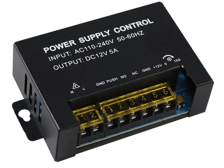
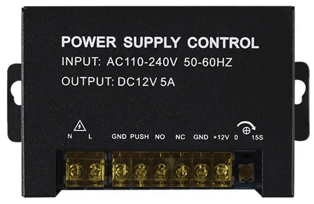
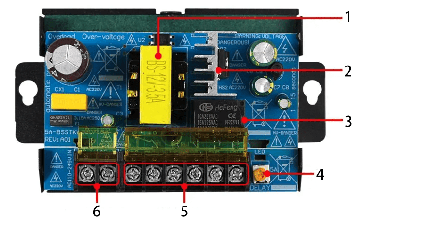
Controller components
1. Transformer: Responsible for converting the AC input voltage (110-240V) to a lower voltage suitable for the rest of the circuit. It provides stable power to the entire device and its connected components.
2. Heat Sink: A component responsible for dissipating heat generated by electronic components such as relays and transformers. The heat sink helps maintain the device's operating temperature, preventing overheating and ensuring its longevity.
3. Relay:
It's used to control the flow of current to connected devices, such as electric locks. The relay is a key component that allows power to these devices to be turned on and off based on control signals.
4. 15S (0-15 seconds): Delay time adjustment knob. Allows you to set the length of time the lock will remain open after activation, from 0 to 15 seconds.
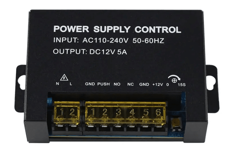
5. Connections
- GND (Ground): Ground (earth). Ensures electrical safety by grounding the device.
- PUSH: Input for the exit button. Connecting to this connector allows you to control the lock using the exit button.
- NO (Normally Open): Normally open output. The circuit closes when activated, which can be used to control electromagnetic locks.
- NC (Normally Closed): Normally closed output. The circuit opens when activated, which can be used to control locks that require the circuit to be opened to unlock.
- +12V: 12V DC power output. Provides power for peripheral devices such as access controllers, card readers, and electromagnetic locks.
- GND (Ground): Additional ground output for peripheral devices.
6. Power supply
- L (Line): Power phase input. Connect the power phase wire (AC 110-240V) to this connector.
- N (Neutral): Power neutral input. Connect the power neutral wire (AC 110-240V) to this connector.

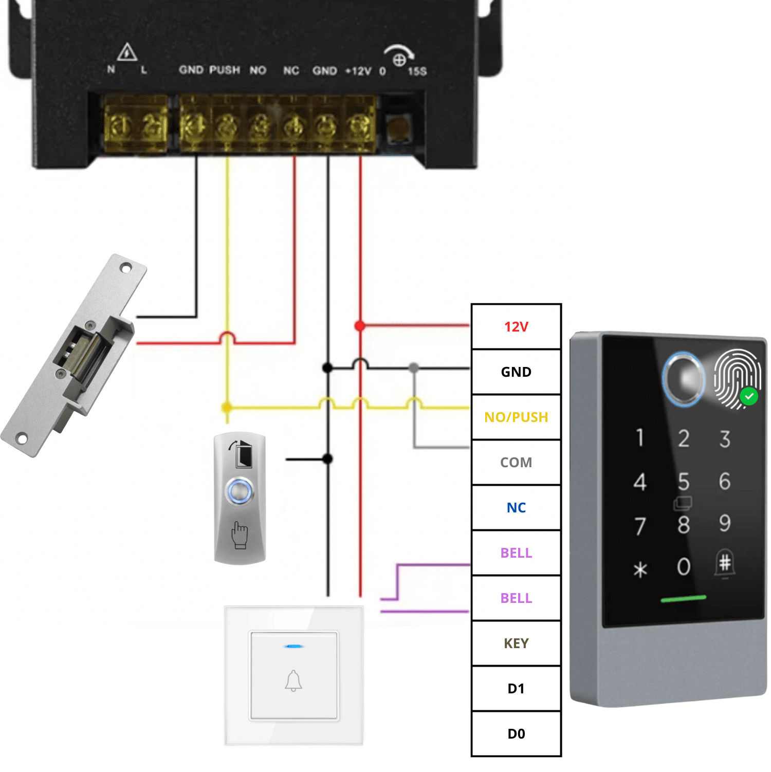
Example power controller connection diagram
1. Power connection:
Power input: The live (blue) and neutral (red) power supply wires (AC 230V 50Hz) are connected to the L and N connectors of the power controller.
2. Connecting the electric strike (electric strike):
NO (Normally Open) Output: The NO output (yellow wire) of the power controller is connected to one end of the electric strike.
COM Output (Common): The COM output (black wire) of the power controller is connected to the other end of the electric strike. When activated, the circuit closes, unlocking the electric strike.
3. Connecting the exit button:
Exit Button: The DOOR EXIT button is connected to the PUSH (yellow wire) and GND (black wire) terminals on the power controller. Pressing the button opens the lock, allowing you to exit the room.
4. Connecting the combination lock:
Code lock power supply: The +12V (red wire) and GND (black wire) outputs of the power controller are connected to the corresponding connectors of the code lock, providing power to the device.
Lock control: The NO/PUSH (yellow wire) and COM (gray wire) outputs of the power supply controller are connected to the corresponding connectors of the combination lock, which allows the lock to be controlled by means of the entered code.
5. Connecting a wired doorbell:
Bell: The bell wires are connected to the BELL connectors (purple wire) on the power controller, which allows an audible signal to sound when an entry is attempted.

Specification
- Input voltage: AC110V-AC240V/50-60HZ
- Output voltage: DC12V
- Instantaneous current: 5A
- DC current: 3.5A
- Operating temperature: -20℃ ~ +60℃
- Working humidity: ≤ 90%
- Delay time: 0~15 seconds (adjustable)
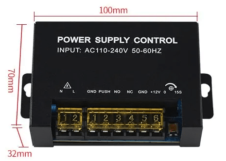
- Dimensions: 100 x 70 x 32 mm

The set includes
- 1x K10 5A Power Controller
- User manual
The Polish manual is available as an electronic download in the attachment. You'll find it below our product description .