
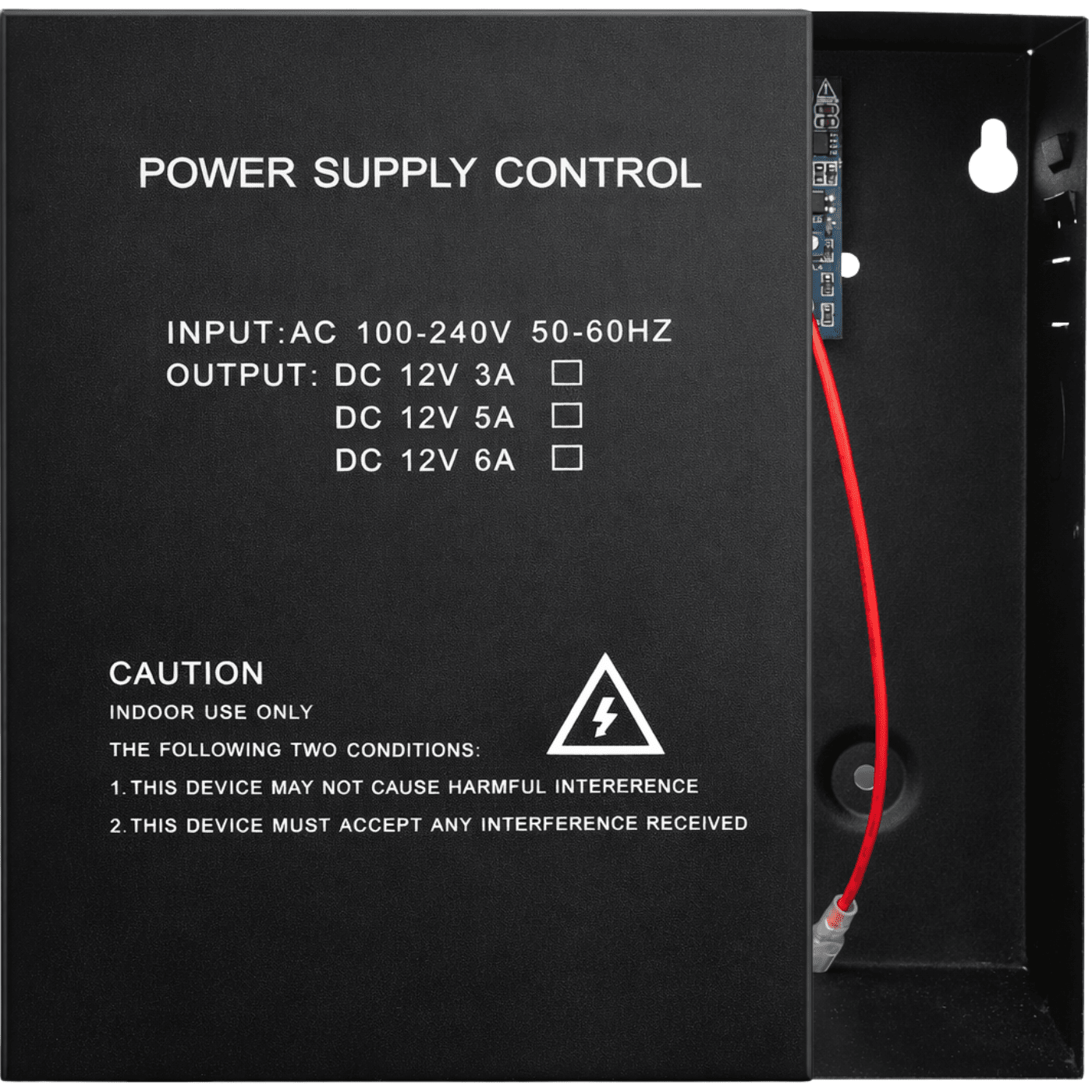
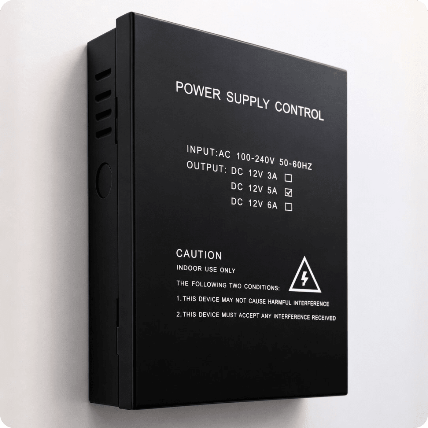
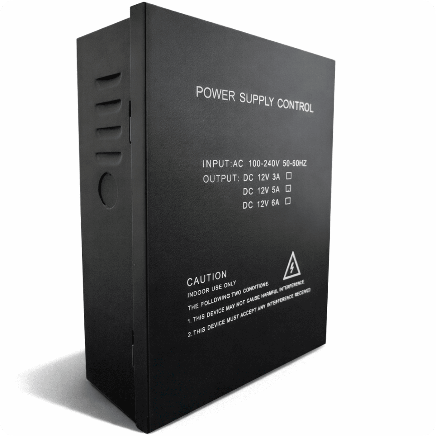

Power Supply PS-902 DC 12V 5A
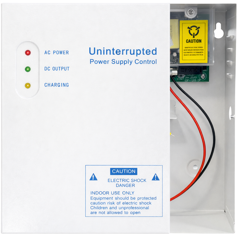


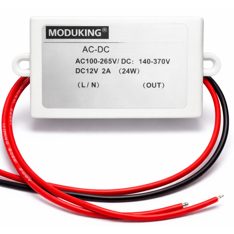




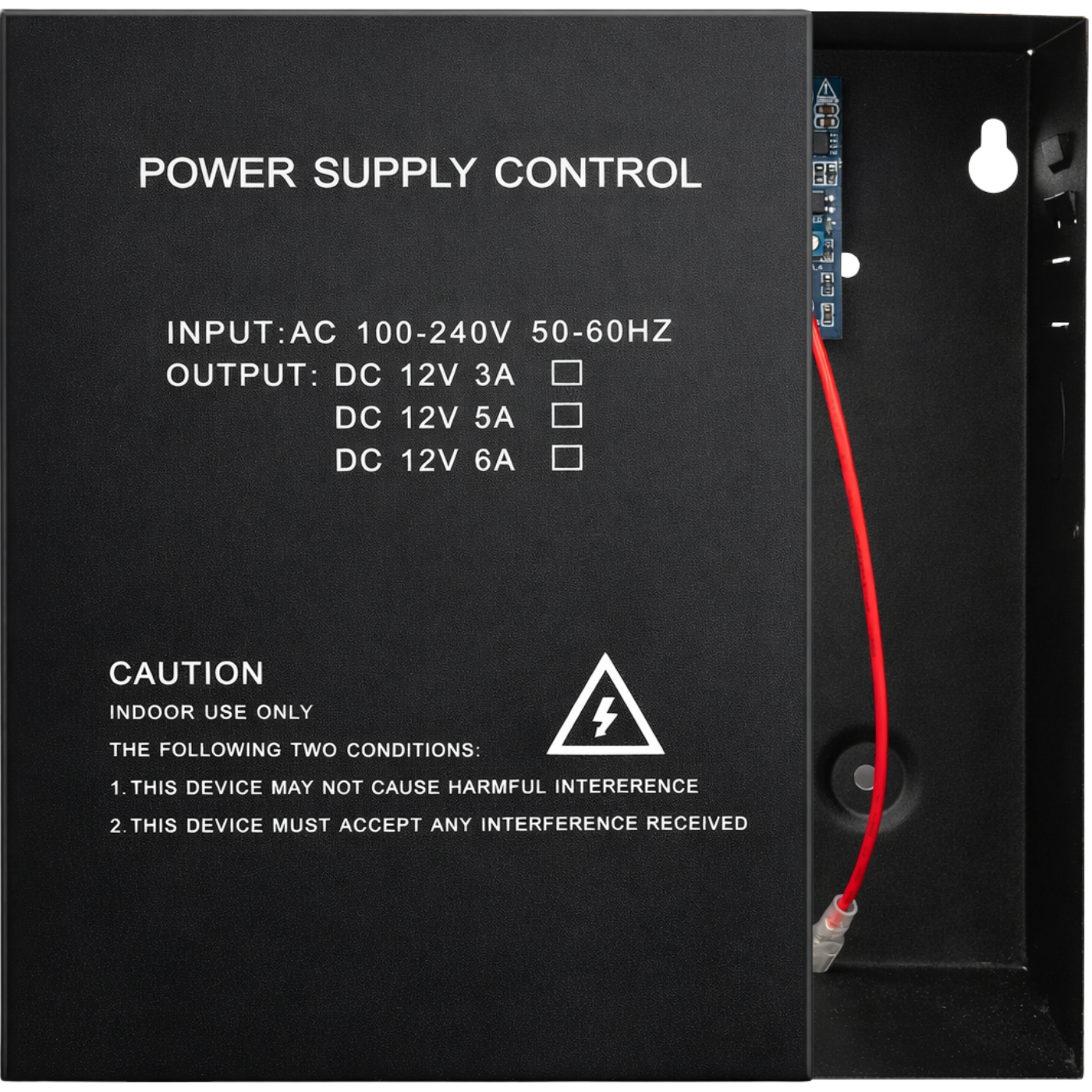
The power supply box from Spreest is a solution designed for access control systems. It provides stable and secure power to devices, as well as a central point for electrical installation.
Additionally, it allows for the connection of emergency power, so the system can operate even in the event of a power outage.
With a 5A output, multiple devices can be connected, allowing it to support, for example, two access control systems simultaneously.
The device is ideal for homes, offices, service buildings, and other facilities.
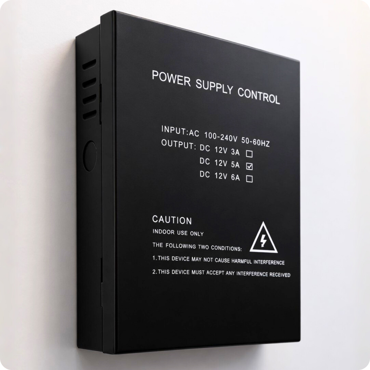
Key Features
1. Emergency Power Connection (UPS / battery) – Keeps the access control system running during a power outage.
2. Supports Multiple Devices Simultaneously – E.g., two access control systems, electric locks, exit buttons, or controllers, thanks to its 5A output.
3. NC / NO Outputs – Compatibility with various types of electric locks.
4. Adjustable Delay Time – Flexibility in lock timing settings from 0 to 15 seconds.
5. Electrical Protections – Protection against overloads and short circuits.
6. Support for Various Devices – Supports electromagnetic locks, access controllers, exit buttons, and doorbells.
7. Robust Construction – Made of durable materials, ensures long-lasting use.
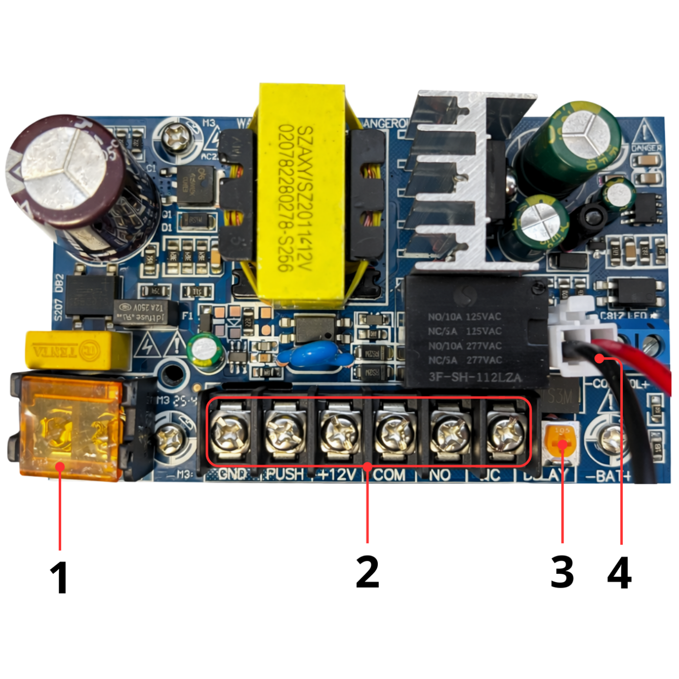
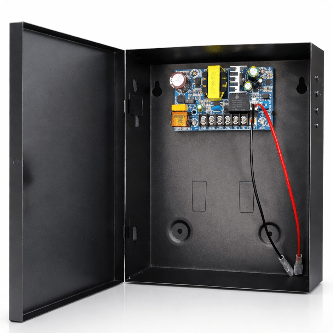
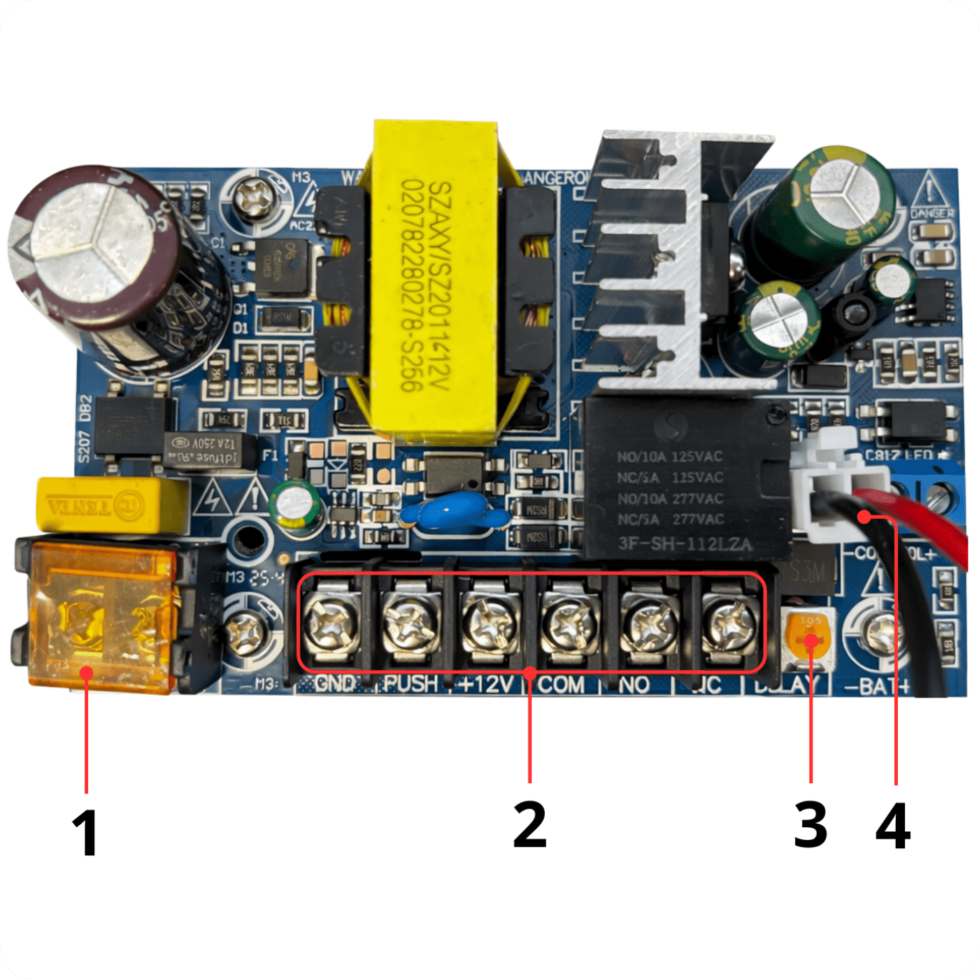
Controller Elements
1. Power Supply:
- L: Power phase input. Connect the power phase wire (AC 100-240V) to this terminal.
- N: Power neutral input. Connect the power neutral wire (AC 100-240V) to this terminal.
2. Connections:
- GND – Ground
- PUSH – Control button input
- +12V – 12V power supply
- COM – Common relay contact
- NO – Normally Open relay contact
- NC – Normally Closed relay contact
3. Delay Time Adjustment Knob: Allows setting the time the lock remains open after activation, from 0 to 15 seconds.
4. Emergency Power:
Connector for connecting a backup battery (typically 12V DC).
- (BAT+) – battery positive pole
- (BAT-) – battery negative pole
The battery ensures the controller operates in the event of a mains power failure (AC). This allows the lock and control system to continue functioning (e.g., enabling door opening).
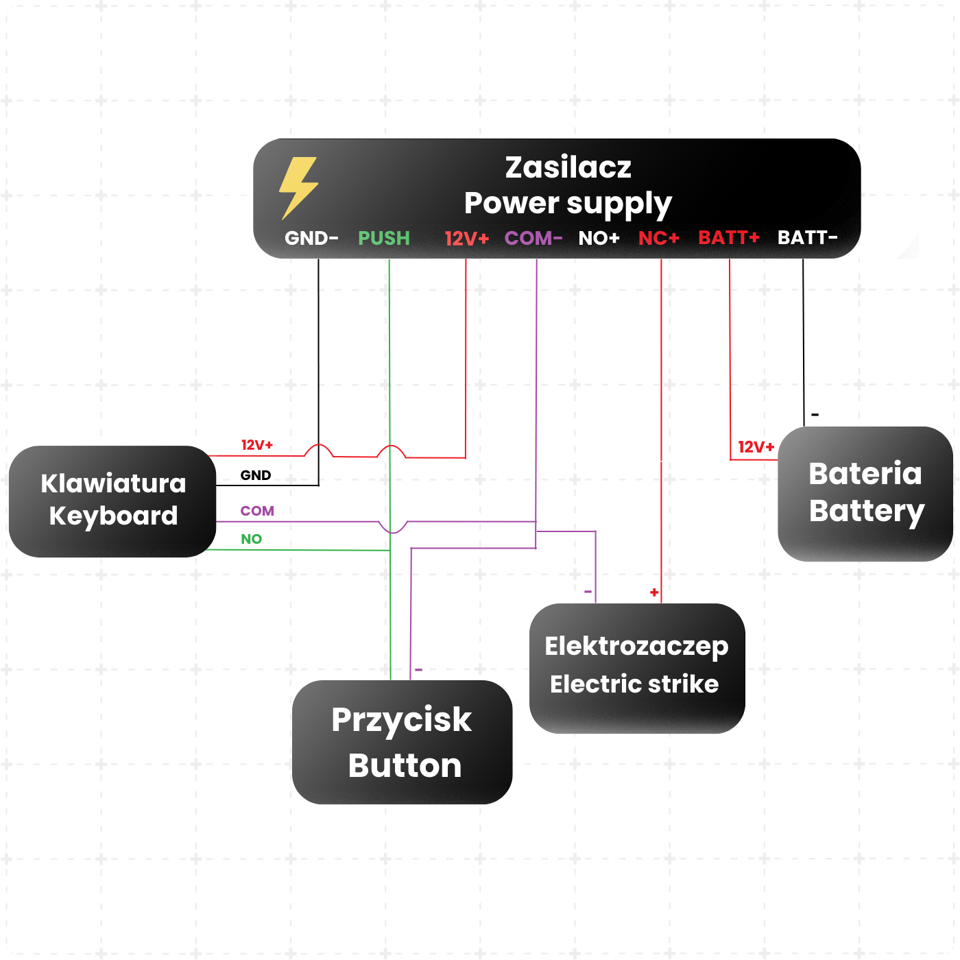
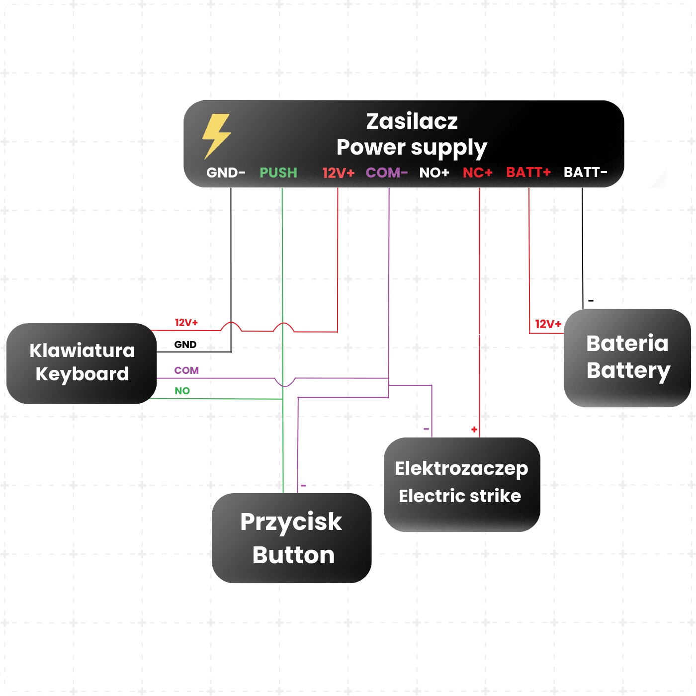
Example Power Supply Connection Diagram
1. Device Power Connection
The +12V output (red wire) from the power supply is used to power access control system devices, such as a code keypad or RFID reader.
The GND terminal (black wire) is the common ground for the installation. The +12V and GND wires should be connected to the appropriate power inputs of the control device.
2. Electric Strike Connection
The electric strike is connected to the +12V (red wire) and NO or NC (black wire) terminals, depending on the type of strike.
After access authorization, the relay contacts (NO/COM or NC/COM) close, powering the electric strike and opening the door.
3. Exit Button Connection
The exit button should be connected to the PUSH (green wire) and COM (purple wire) terminals.
Pressing the button shorts PUSH to ground, causing immediate door unlocking.
4. Keypad / Access Controller Connection
The keypad should be connected to the terminals:
- +12V (red wire)
- GND (black wire)
- COM (purple wire)
- NO (green wire)
After successful user authorization (code/card), the relay is activated, and the door opens.
5. Relay Operating Mode (NO / NC)
The power supply has NO (normally open) and NC (normally closed) outputs:
- NO – Voltage appears only after shorting on the PUSH contact (most commonly used)
- NC – Voltage disappears only after shorting on the PUSH contact
- (security systems)
6. Battery Connection (Emergency Power)
A 12V battery can be connected to the BATT+ (red wire) and BATT- (black wire) terminals.
The battery ensures the system operates in the event of a mains power failure.
Technical Specifications
- Input Voltage: AC100V-AC240V / 50-60HZ
- Output Voltage: DC12V
- Instantaneous Current: 5A
- Constant Current: 3.5A
- Operating Temperature: -20℃ ~ +60℃
- Operating Humidity: ≤ 90%
- Delay Time: 0~15 seconds (adjustable)
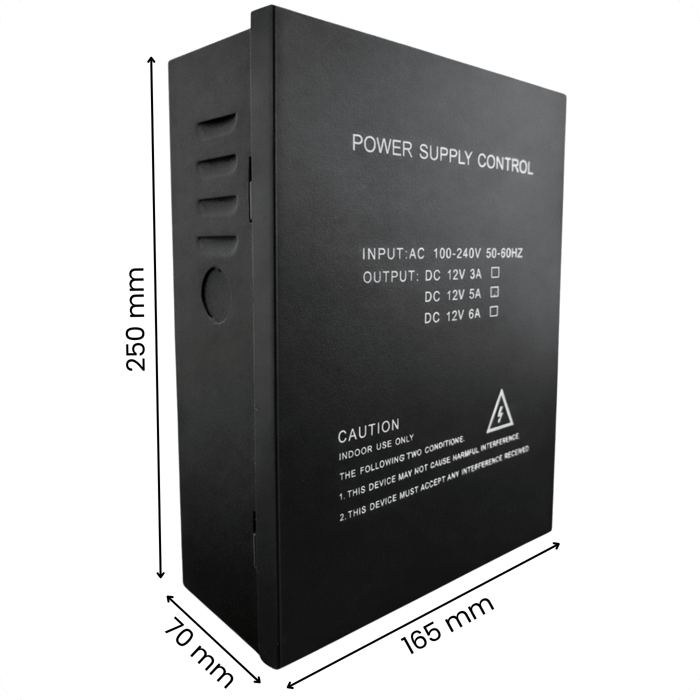
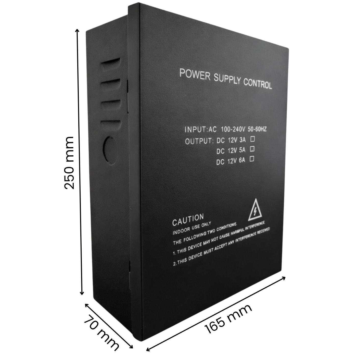
- Dimensions: 165 x 70 x 250 mm
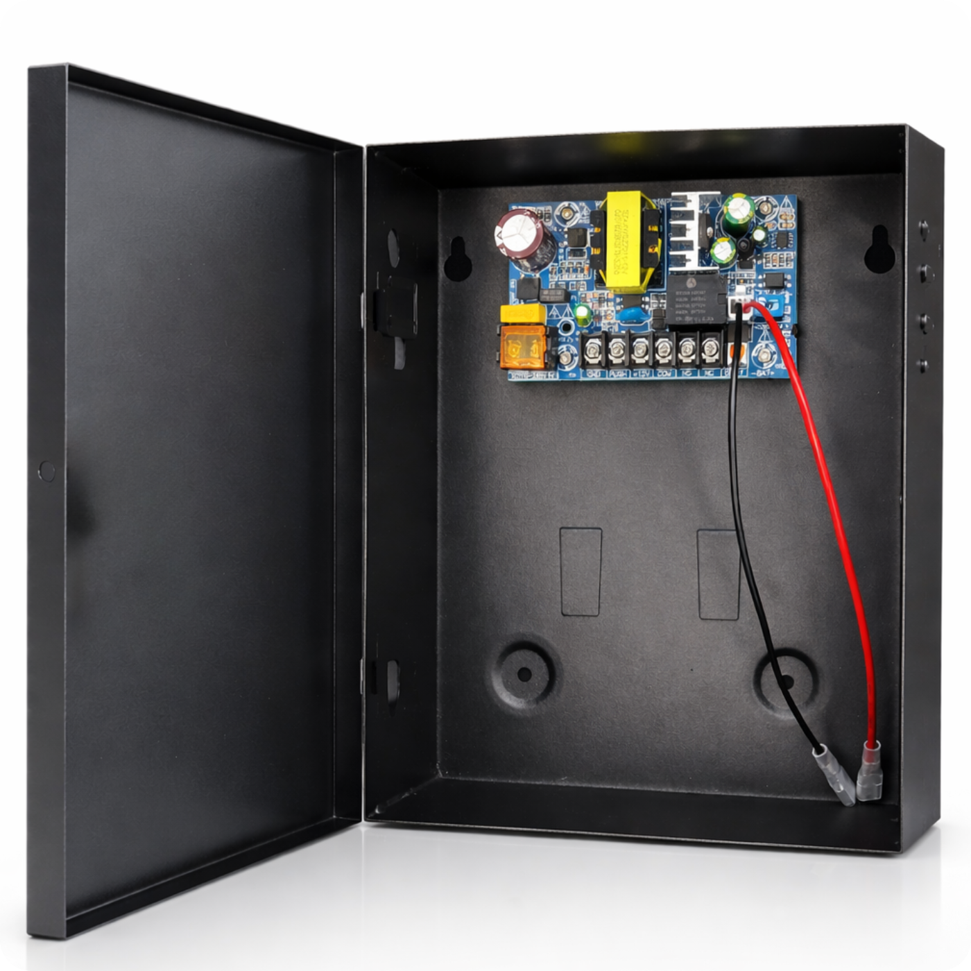
Set Includes
- 1x PS-902 DC 12V 5A Power Supply Box
- 1x User Manual