
Exit button S28L Monostable
Najniższa cena z 30 dni przed obniżką: 25,99 zł
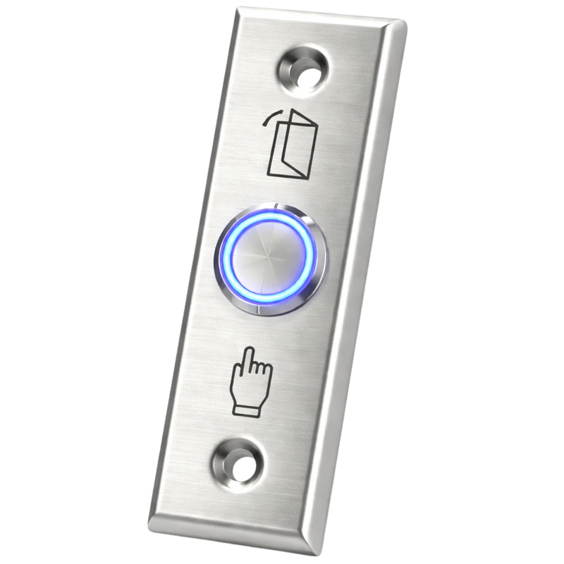


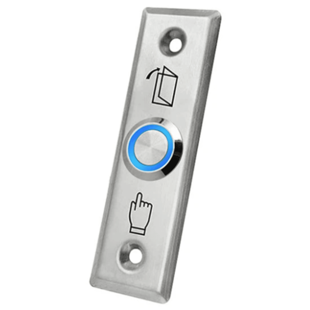
The Spreest exit button for access control systems is a robust and reliable solution that allows for quick and easy opening of the connected electric strike. Designed with durability and elegance in mind, this button is the perfect complement to any access control system.
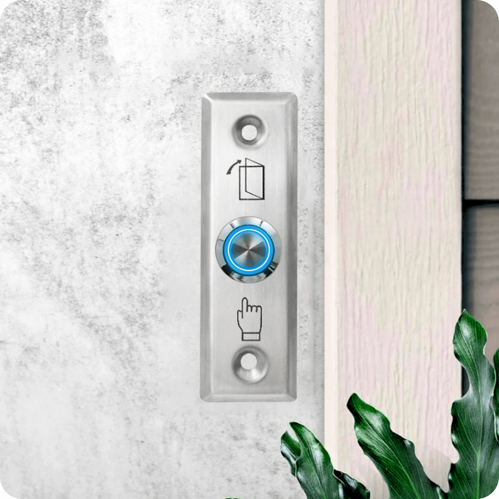
An additional convenience is the button backlight , which is useful in low light or at night .

Specification
- Contact type: NO, monostable
- Product Type: Exit Button External/Internal
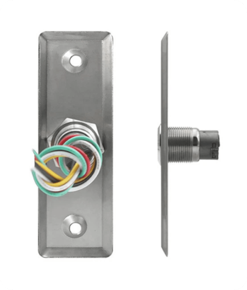
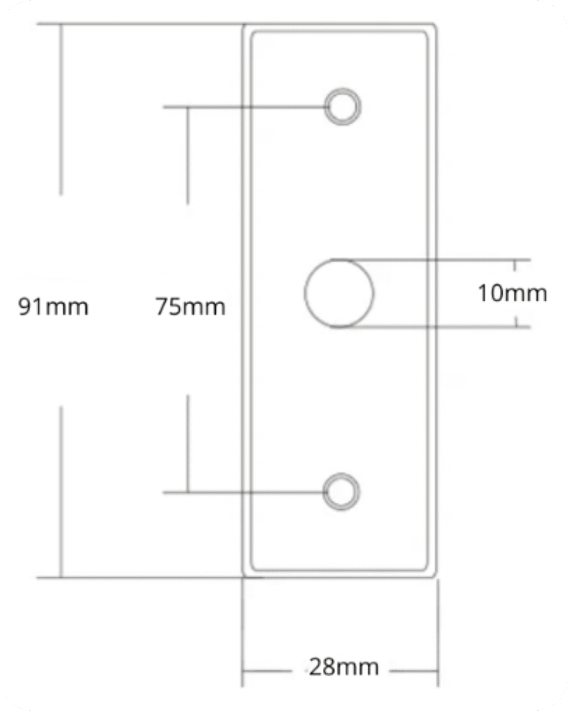
- Installation: Surface-mounted
- Contact load capacity: 3 A / 12-24 V AC/DC
- Material: Stainless steel
- Protection class: IP40 (recommended for indoor use)
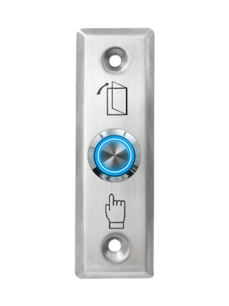
- Button Backlight: Yes
- Color: Silver
- Design life: 500,000 presses
- Weight: 0.03 kg

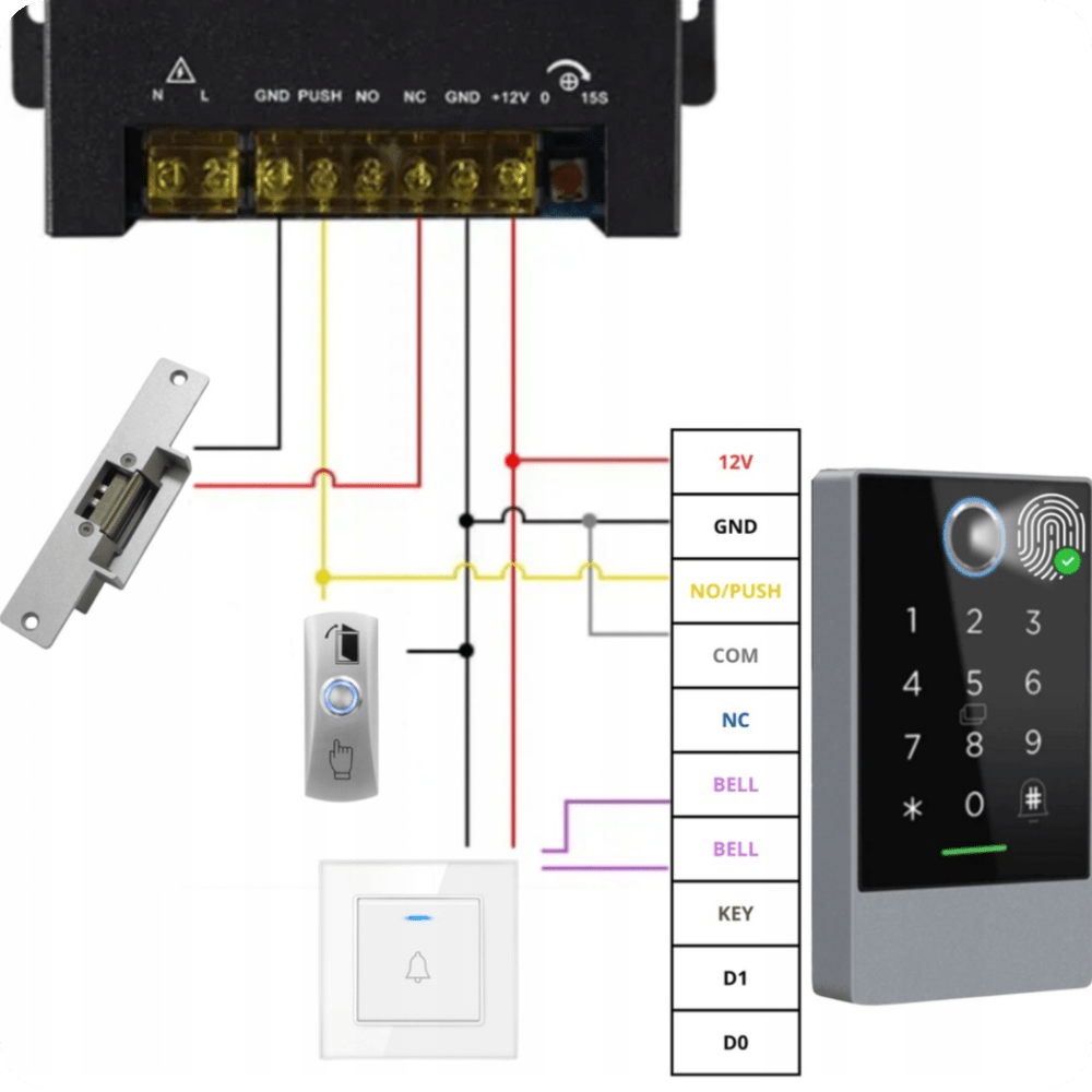
An example scenario for integrating an exit button with an access control system
1. Power connection:
Power input: The live (blue) and neutral (red) power supply wires (AC 230V 50Hz) are connected to the L and N connectors of the power controller.
2. Connecting the electric strike (electric strike):
NO (Normally Open) Output: The NO output (yellow wire) of the power controller is connected to one end of the electric strike.
COM Output (Common): The COM output (black wire) of the power controller is connected to the other end of the electroslam. When activated, the circuit closes, unlocking the electroslam.

3. Connecting the exit button:
Exit Button: The DOOR EXIT button is connected to the PUSH (yellow wire) and GND (black wire) terminals on the power controller. Pressing the button opens the lock, allowing you to exit the room.
4. Connecting the combination lock:
Code lock power supply: The +12V (red wire) and GND (black wire) outputs of the power controller are connected to the corresponding connectors of the code lock, providing power to the device.
Lock control: The NO/PUSH (yellow wire) and COM (gray wire) outputs of the power supply controller are connected to the corresponding connectors of the combination lock, which allows the lock to be controlled by means of the entered code.
5. Connecting a wired doorbell:
Bell: The bell wires are connected to the BELL connectors (purple wire) on the power controller, which allows an audible signal to sound when an entry is attempted.

The set includes
- 1x Exit Button EB-12A
- 1x Set of mounting accessories
Our offer includes other complementary products for access control systems.